-
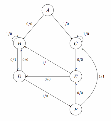
Complete the state transition table for this finite state
machine, using the state assignment:
A = 000, B = 010, C = 001, D = 110, E = 011 and F = 111.
(Note that two bit patterns are not used.)
Use this table: hw4-1.pdf.
-
Write out a Boolean expression for s2', s1',
s0' and z. Start with either the
disjunctive normal form (a.k.a. sum of products)
or the conjunctive normal form (a.k.a. product sums).
Simplify the formula as much as you can and write down
your final answer below the table in
hw4-1.pdf.
Show all your work in separate sheets of paper.
-
Construct the finite state machine in Logisim using
three D flip flops to store the state. Save your circuit,
transfer the file to GL and submit using:
submit cs313 hw4 hw4-1.circ - Turn in your paper-based work (parts a & b, including work for part b) in class.
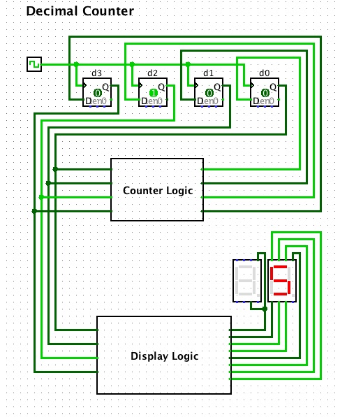
- Complete the state transition table
for your modulo 10 counter. Since 10 is between 8 and 16,
you will need 4 bits to count from 0 to 9.
Use the natural state assignment, that is
0 should be 0000, 1 should be 0001, ... 5 should be 0101
... and 9 should be 1001.
Use this table: hw4-2.pdf.
-
Write out a Boolean expression for s3', s2',
s1' and s0'. As in Question 1,
show all your work and write down your answer below the
table in hw4-2.pdf.
-
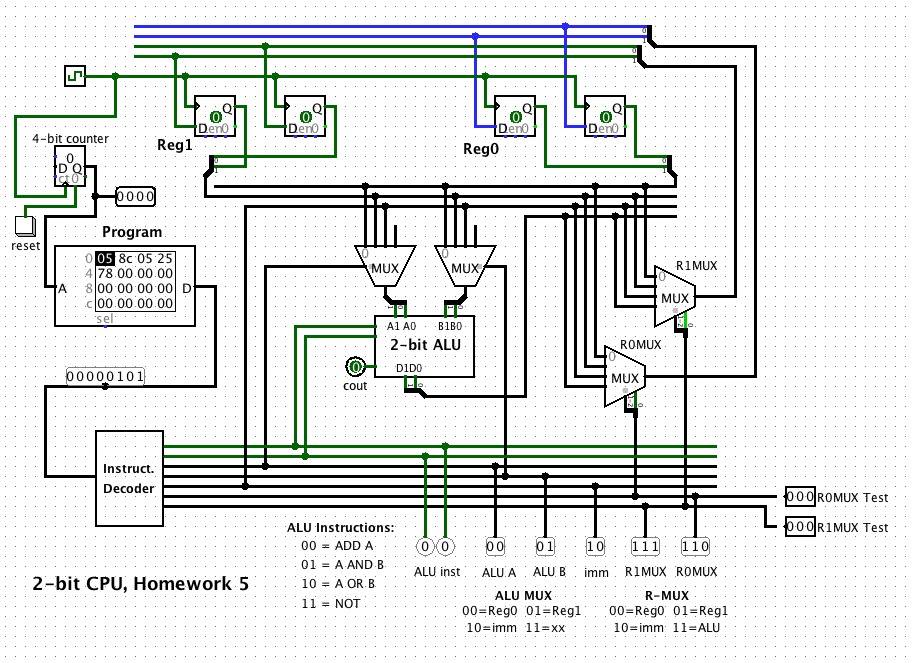
As in Question 1, implement your finite state machine
in Logisim. Use D flip flops, you should have 4 flip flops.
Then, save and submit the circuit file on GL:
submit cs313 hw4 hw4-2.circ - Turn in your paper-based work (parts a & b, including work for part b) in class.
 to Fall 2012 CMSC 313 Homepage