The Assignment
This assignment will build your assignment 4 OpenGL code (or mine, if yours was not working) by implementing two methods to add apparent detail without adding additional geometry. The first of these, Normal Mapping, modifies the normals used for shading according to data stored in a texture. The second, Relief Mapping (also known as Parallax Occlusion Mapping), uses a form of ray tracing to compute the intersection with an imaginary surface below the polygonal surface. Both techniques work best seen roughly head-on and break the illusion of additional detail when viewed glancing angles.
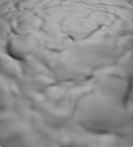
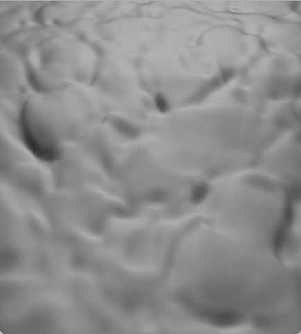
| Geometry | Normal Map | Relief Map | |
|---|---|---|---|
| Untextured |  |
 |
 |
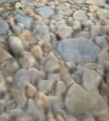
| Textured | 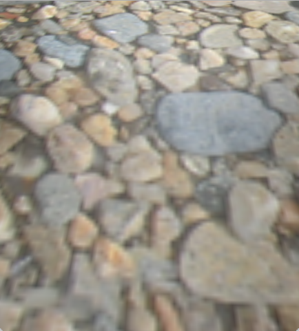 |
 |
 |
Spaces
You will need to do some conversions between coordinate spaces. These are the spaces in our application
- Terrain model space: The X and Y axes are horizontal and the Z axis is vertical. The X axis points in the U texture direction and the Y axis in the V texture direction. Mine has the origin in the middle of the terrain. Yours may have a different origin, but the origin should not matter as long as the directions are consistent. We do not have a world space, but if there were additional objects with their own model spaces, terrain space would be a good candidate for an overall world space.
- View space: This is not a built-in OpenGL space, but our application does define one. Our view space has the eye at (0,0,0). The X axis points toward the right side of the view, Y points toward the top of the view, and Z points backwards. In shader code, you can use
modelViewMatrixto convert points in model space into view space, andmodelViewInverseto convert points in view space back into model space. - Clip space: OpenGL clip space is used for the built-in vertex shader variable
gl_Position. Also known as Normalized Device Space, vertices are transformed into this space for display. In this space, the view frustum is warped into an axis-aligned cube from (-1,-1,-1) to (1,1,1). You can convert points in view space to clip space withprojectionMatrixor from clip space back to view space withprojectionMatrixInverse. - Screen space: OpenGL screen space is available in the fragment shader using the built-in variable
gl_FragCoord. The Z component is depth, while the X and Y components are screen pixel location with 0,0 at the upper left corner. To convert from screen space back to clip space you would need to create a viewport transform from the window size. - Tangent space: This is defined per point on the surface. It has the Z axis pointing in the direction of the normal, X pointing tangent to the surface in the direction of increasing U texture coordinate, and Y pointing tangent to the surface in the direction of increasing V texture coordinate.
To complete this assignment, you will need to construct the 3x3 TBN matrix to convert between view and tangent space. The columns of this matrix are the view-space Tangent, Bitangent (secondary tangent), and Normal. The third column of this matrix is the view-space normal, which you already have. The second column should be a view-space tangent vector pointing in the V texture coordinate direction. You know the V direction is (0,1,0) in model space. That can be transformed into view space, projected onto the plane perpendicular to the normal using Gram-Schmidt or cross products, and normalized. Similarly, the first column should be a view-space tangent vector pointing in the U direction. This will produce a TBN matrix to convert tangent space vectors to view space. Since this matrix is constructed to be orthogonal, its inverse is its transpose, so can be trivially used to also convert view space vectors into tangent space.


Relief Map
Relief mapping is a technique that adds even more convincing small surface detail by computing the intersection of the viewing ray with an imaginary surface beneath the geometric surface. Our surface will be defined by a greyscale height texture. You will also need to define a relief map height scale. Choose this to make the rock bumps a realistic height.
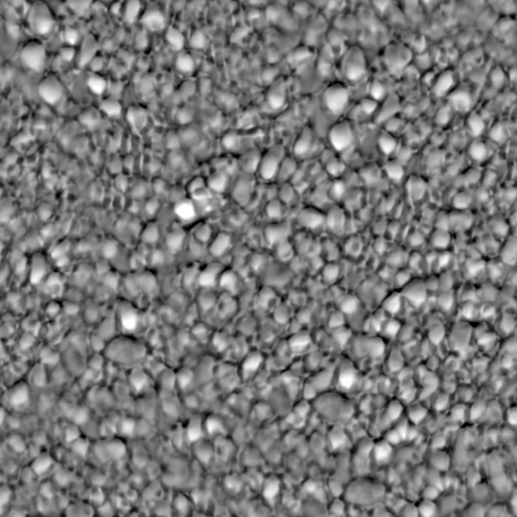
height texture

You will need to add code to load the pebbles-bump.ppm file. In the shader, compute the viewing ray (this is easy in view space), and use the TBN matrix to compute that ray to tangent space. We will use the same approach as the 2005 relief mapping I3D paper to find the intersection of the viewing ray with the relief surface. That takes up to 10 linear steps looking for the first place the depth of the ray beneath the polygonal surface crosses below the relief surface, then does five steps of binary search to refine the intersection point. Each step updates the texture coordinate U/V and ray depth at that texture coordinate and compares it to the depth from the relief texture.

Once you find the U/V of the relief intersection, use the texture and normal map at that U/V for shading.
Add code to toggle the relief map on and off by pressing the "H" key (for (H)eight, since R is already used for shader (R)eload).
Extra credit
For up to 10 points of extra credit, once you have found the relief mapping intersection point, take a fixed number of linear steps toward the light to see if the intersection point should be in shadow or not. This only captures local shadowing by the relief surface, but still adds significant realism to the surface.
For up to 10 points of extra credit, create a new loader for the RGB_ALPHA PAM image file format, and create a PAM file that packs the normal map into the RGB channels and the bump map into the A channel of a single texture. Use this single texture in your normal and relief map shader computations.
Extra credit is only available if you submit by the original deadline or use your free late. If you submit late with the late penalty, you will not be eligible for any extra credit points.
You are also only eligible for extra credit if you tell us you did the extra credit in your assn5.txt and where to find the relevant changes in your code.
Strategy
Do the normal map first. For relief mapping, do the linear stepping part before the binary search refinement.
One of the primary strategies for shader debugging is outputing values to color and interpeting the results. Remember that values less than 0 will appear the same as 0, and values greater than 1 will appear the same as 1. Some useful strategies for remapping colors into visible ranges for debugging
- Rescale x ∈ [-1,1] to x' ∈ [0,1] using x' = x * 0.5 + 0.5
- Rescale x ∈ [a,b] to x' ∈ [0,1] using x' = (x - a)/(b - a)
- Rescale x ∈ [0,∞] to x' ∈ [0,1] using x' = x / (1 + x)
- Rescale x ∈ [-∞,∞] to x' ∈ [-1,1] using x' = x / (1 + abs(x))
- step(), >, or < can tell you when a value is negative, positive, or crosses some threshold
- You can put different views of the same variable into red, green, and blue. I often like red for negative, green for positive, and blue for some mapping of the absolute value. This results in black if exactly 0, red to magenta for negative values, and green to cyan for positive values.
What to turn in
Turn in this assignment electronically by pushing your source code to your class git repository by 11:59 PM on the day of the deadline and tagging the commit assn4. Do your development in the GLapp directory, continuing to modify the code there. It is not necessary to make a copy. Version control allows us to check out the assignment 4 version for grading while you work on assignment 5, even if you commit and push along the way.
Also include an assn5.txt file telling us about your assignment. Include your name and campus ID at the top of this file. Do not forget to tell us what (if any) help you received from books, web sites or people other than the instructor and TA.
Check in along the way with useful checkin messages. We will be looking at your development process, so a complete and perfectly working assignment submitted in a single checkin one minute before the deadline will NOT get full credit. Individual checkins of complete files one at a time just before the deadline will also NOT get full credit. Do be sure to check in all of your source code, CMakeLists.txt, and updated .gitignore file, but no build files, log files, generated images, zip files, libraries, or other non-code content. If you created your own PAM for the extra credit, check that in as well.
Be sure to include the details of the system you used for the assignment in your assn5.txt in case we have problems.