3D Viewing
-
Specification of a View Volume
View Plane (projection plane) is defined by :
VRP = View Reference Point
VPN = View Plane Normal
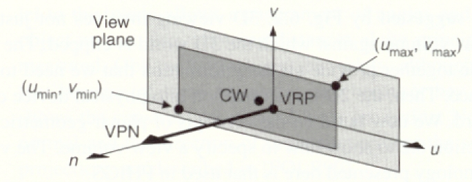
Window on the View Plane:
To specify a min & max value for 2 orthogonal directions
on the view plane, we introduce the
Viewing Reference Coordinate(VRC) System.
-
then define
umin, umax, vmin,vmax
View Reference Coord. system(VRC):
Origin = VRP
n axis: VPN
v axis: Projection of View Up Vector
(VUP) onto the View Plane
u axis: an axis mutually orthogonal to n &
v to make a RH coordinate system

-
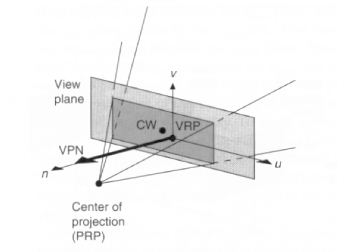
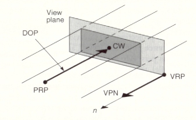
Projection Reference Point (PRP) - defines the center
of projection and the
direction of projection (also called COP)
-
specified in VRC, not world coordinates
-
Projection type
-
The View Volume is then
the portion of the world that is to be projected onto
the projection plane and then transformed to the viewport.
-
Perspective View volume: truncated
pyramid with apex at the PRP (COP) and the
edges passing through the corners of the window.
-
Introduce hither(front)
and yon(back) clipping planes
to give a finite view volume.
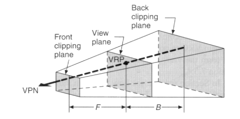
-
Clip away objects that are too close to the PRP and
would make the rest of the scene hard to understand.
-
Clip away objects that are very far away and won't
add any useful information to the final scene.
This will reduce the computational expense of computing
the final image.
-
Default Viewing parameters in Normalized Projection coordinates(NC)
or WC:
VRP(WC)=(0,0,0),VUP(wc)=y,VPN(wc)=Z,
PRP(nc)= (.5, .5, 1)
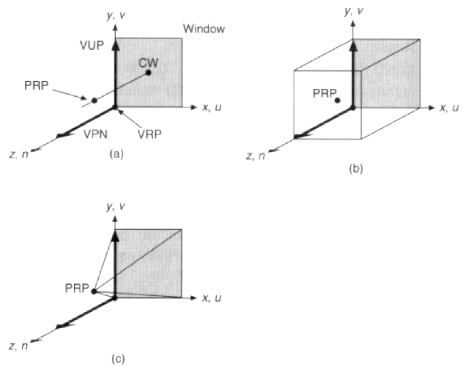
-
(a) The Default Viewing Specification
-
(b) Default Parallel Projection View Volume
-
(c) Defaul Perspective Projection View Volume
Basic Case
-
Assume VP is normal to the Z axis
-
The projection plane is at z=d
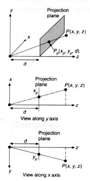
Xp/d = x/z
Yp/d = y/z
Xp = x/ (z/d) Yp = y/(z/d)
In a 4x4 Matrix, this becomes
| 1 0
0 0 |
Mper= | 0 1 0
0 |
| 0 0
1 0 |
| 0 0
1/d 0 |
[X Y Z W]T = Mper * [x y z 1]T
= [ x y z z/d]
Now projecting back to 3 space (divide by w)
Projections and the Canonical View Volume
-
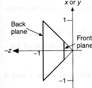
The canonical perspective view volume:
-
6 clipping planes:
x=z, x= -z,
y=z, y=-z,
z=zmin,
z= -1
-
Why clip against this?
-
So, we need to find the transformation that takes our
perspective view volume and
transforms it to the canonical view volume
-
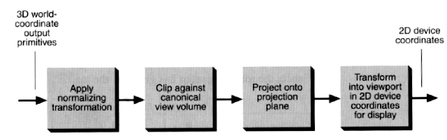
In Summary,
3D Viewing Process
The Perspective Projection
-
We want to find the Normalizing transformation Nper
that takes our view volume and transforms it into
the canonical view volume.
-
Nper is derived from the following:
-
1) Translate VRP to the origin: T(-VRP)
-
2) Align VRC with World Coordinates
Rotate VRC such that VPN becomes the Z axis, the u axis
->x axis, v axis ->y axis: R
-
3) Translate so that COP (PRP) is at the origin:
T(-PRP)
-
4) Shear so that the center line of the view volume
becomes the Z axis: Sh
-
5) Scale such that the view volume becomes perspective canonical
view volume : Sc
-
What is the Matrix R in (2) above?
R = [Rx 0], where Rx
= VUP x Rz (normalized)
[Ry 0], where Ry = Rz x Rx (normalized)
[Rz 0], where Rz = VPN (normalized)
[0 0 0 1]
Let's look at all of these steps again:
-
1) Translate VRP to the origin: T(-VRP)
-
2) Align VRC with World Coordinates
Rotate VRC s.t. VPN becomes the Z axis and the u axis
->x axis, v axis ->y axis: R
-
R can be gotten from the rotations that we looked at earlier:
3 rotations will be needed to align the nuv axis with
the xyz axis.
-
It can also be found from the properties of orthonormal
matrices:
How do we represent the xyz axis in the new
space.
The representation of these will be the row vectors
in the transformation matrix.
-
3) Translate so that PRP (COP) is at the origin: T(-PRP)
(This space is sometimes also called eye space since
the COI is at the origin)
-
Now the coordinate systems are aligned and everything
is set up to do perspective easily
-
The following transformations make the clipping easy.
-
4) Shear so that the center line of the view volume becomes
the Z axis: Sh
This is needed to align theview volume center line
with the Z axis.
If the VPN = DOP (line of sight), this is not
needed.
What are the shear values?
DOP = CW -PRP
We want DOP' to be [0 0 dopz 0]T
= [SH] *DOP
What is this shear transformation going to do?
It is going to create
This resulting space is normally referred to as eye
space:
COP (eye pt) is at the origin looking down the -Z
axis.
Perspective is easy to do here, since the projection
plane in normal to the Z axis & the COP is the origin.
-
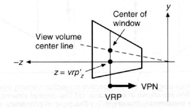
5) Scale such that the view volume becomes perspective
canonical view volume :
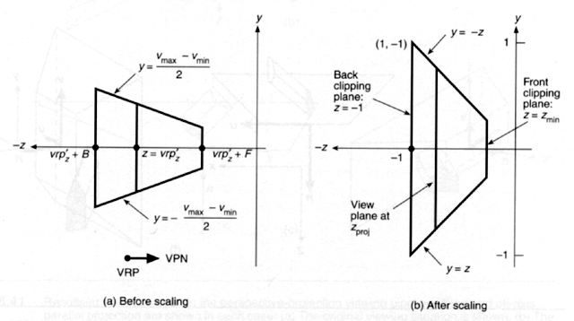
Note: In this figure F and B have opposite signs; therefore, they are
on opposite sides of the view plane.
We want to scale so that the sides have unit slope:
Scale the window so that it's half-height and half-width
have are both -vrp'z:
Sx = -2 * vrp'z/ (umax -umin)
Sy = -2 * vrp'z/ ((vmax -vmin)
Then we scale the window so that yon clipping plane,
now at z= vrp'z + yon
becomes z=-1:
scale by -1/ (vrp'z +yon)
The final combined scale factors are:
Sx = 2 * vrp'z/ ((umax
-umin)*(vrp'z +yon))
Sy = 2 * vrp'z/ ((vmax -vmin)*(vrp'z
+yon))
Sz = -1/ (vrp'z +yon)
So the final transformation is:
Nper = Sc * SH * T(-PRP) * R *
T(-VRP)
After the transfomations, the bounds of the view volume
are:
zmin >= z >= -1
-z >= y >= z
-z >= x >= z
where zmin = -(vrp'z + hither)/(vrp'z
+ yon)
-
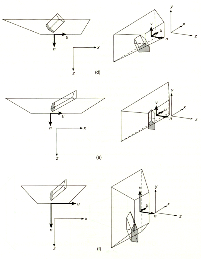
Example of the Normalizing Perspective View Transformation
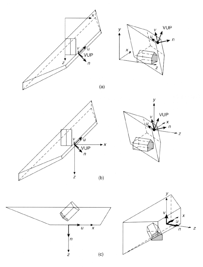
(a) Original View
(b) VRP Translated to the origin: T(-VRP)
(c) VRC and World Coordinates systems aligned: R
(d) PRP (COP) has been tranlated to the origin: T(-COP)
(e) After shear to align DOP with Z axis: SH
(f) After Scaling to canonical perspective view volume: S
View parameters: VRP=(1.0, 1.275, 2.6), VPN=(1.0, 0.253, 1.0), VUP=(0.414,
1.0, .253), PRP=(1.6,0.0, 1.075)
F=0, B=-1.2, Window=(-1.325, 2.25, -0.575, 0.575)
-
To make the clipping test even simpler, can
add the
transformation to the normalized
parallel
projection coordinate system in
homogenous
coordinates. We will skip this.
RESULTING OPERATIONS NEEDED:
-
1) Transform the points to world space.
-
2) Read in & Calculate the viewing parameters,
VRP, PRP(COI), VPN, VUP, VRC (n,u,v), umin, umax,
vmin, vmax.
-
3) Calculate T[-VRP], R, and T[-PRP]
-
calculate vrp' = T[-PRP]*R* T[-VRP]*vrp
-
This is needed in the next step.
-
4) Calculate SH & Sc
-
5) Calculate Nper = Sc*SH*T[-PRP]*R* T[-VRP]
-
6) Transform points by Nper
-
7) Clip points against the canonical view volume.
-
8) Transform points by Mper
-
10) Perform the window to viewport mapping from lab 2.
Use the width & height of the viewport as width
and height of the original window.
How To Implement 3D Perspective Viewing
Reminder about Spaces
-
The COP (PRP) is in world coordinates in our data files,
-
Our model assumes it is in VRC coordinates.
-
You need to convert it. The following will do it:
COP.x = (COP
- VRP) · Rx
COP.y = (COP
- VRP) · Ry
COP.z = (COP
- VRP) · Rz
where Rx, Ry, and Rz are the basis of the VRC in world
coordinates
(see above in notes), the components
of the R matrix.
Window to Viewport Transformation
-
The transformation by Nper results in a canonical
view volume with the projection plane now being a square, with sides of
length -2*Zproj.
-
At this point, the original window has been transformed into
a square. The window-to-viewport transformation needs to get it back to
it's original shape.
-
Think of this as a 2 step process:
Use the size of the window given in the
input file and the
drawing area on the Edge display to calculate the size
of the viewport:
1) Calculate
ratio = (wumax-wumin) / (wvmax-wvmin)
a)
This is now used to get the height and width of the
viewport, knowing that the size of the drawing area is
600x500 (600/500 = 1.2) -- assumes a 50 pixel blank border.
b) If ratio
> 1.2 then
width = 600, height = 600 / ratio
Else
height = 500, width = 500*ratio.
c) Given this
height and width, calculate viewport
boundaries
Umin, Umax, Vmin, and Vmax as follows:
Umin = 450 - width/2
Umax = 450 + width/2
Vmin = 300 - height/2
Vmax = 300 + height/2
2) The ``new window'' in the window to viewport
transformation is the transformed window on the projection plane:
xmin = zproj,
xmax = -zproj,
ymin = zproj,
ymax = -zproj.
The viewport is specified by the above calculated Umin,Umax,
Vmin, andVmax.
The Order of Operations:
-
Save a copy of PRP(COP) in world space for backface and lighting
calculations.
-
Calculate PRP(also called COP) in VRC coordinates.
-
Calculate Sh and Sc,
remember that CW has a z component of 0 and DOP = CW-PRP(after
R & T(-vrp)).
-
Calculate Nper = Sc*SH*T(-prp)*R*T(-vrp). (all of these are
4x4 matrices)
-
Calculate zproj = - vrp'z / (vrp'z
+ yon)
-
Calculate Window to viewport transformation as described
above.
-
Calculate Mper with d = zproj.
-
Initialize Transform = Identity
-
Loop for each rotation and scale the user clicks on
-
Calculate the Rotation or Scale matrix for rotation/scale
about the axis that was specified, call it T1.
-
Set Transform = T1*Transform
-
Transform points to world space, then to normalized canonical
view volume:
pnts' = Nper*Transform*pnts.
-
Or, if doing illumination and backface rejection,
-
Transform to world space, backface reject, calculate illumination,
then transform to normalized canonical view volume.
-
Perform window to viewport mapping.
end for each rotation/scale
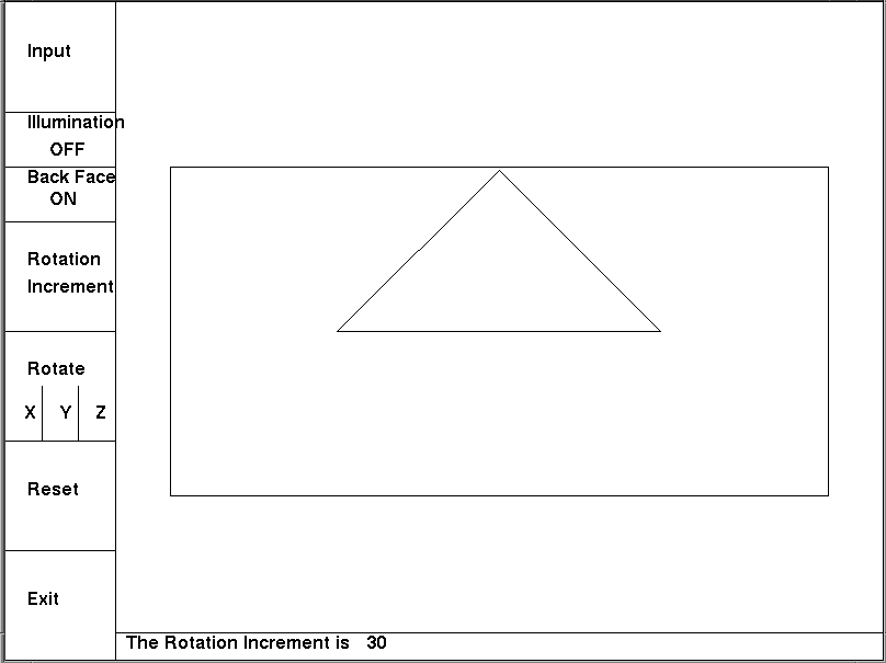
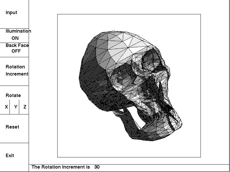
Example Wireframe Perspective Viewing
-
A Simple Triangle with an easy view specification
-
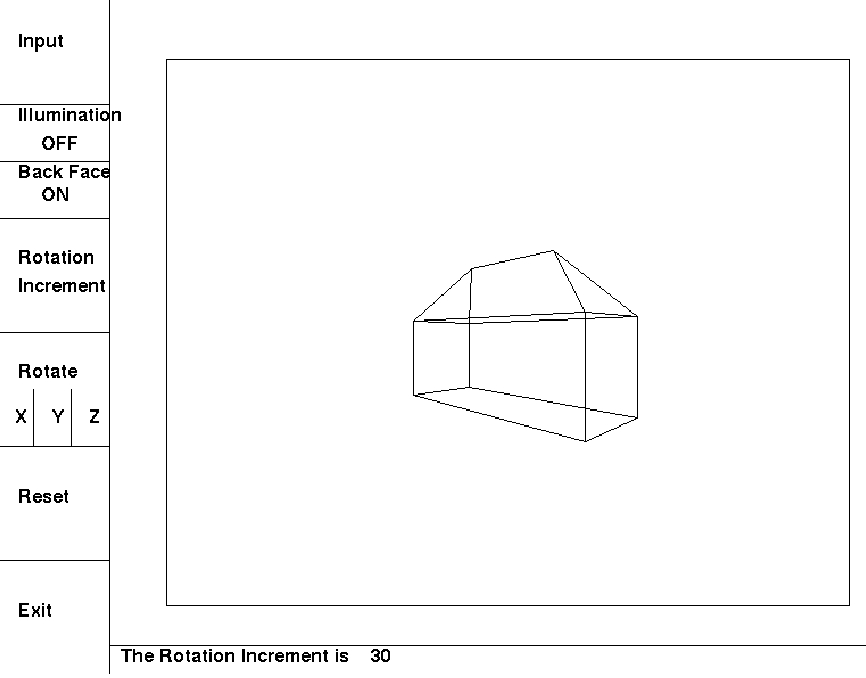
An Example House
-
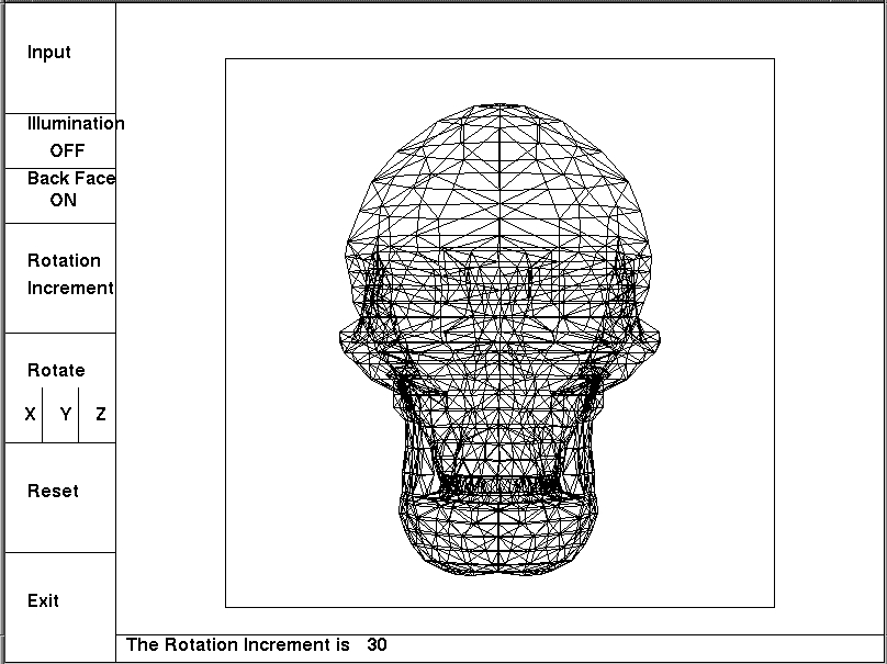
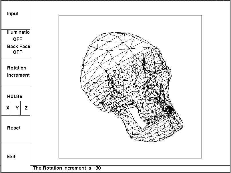
A Skull Example
3D Clipping
-
We will look at entending Sutherland-Hodgman to 3D.
-
Others can be extended just as easily.
-
For perspective canonical view volume, the tests
are real simple:
Inside if:
Left: x > z
Right: x < -z
Bottom: y > z
Top: y < -z
Back: z > -1
Front: z < zmin
Sample Intersection Calculation:
use parametric representation of the line:
x = x0 + t (x1-x0) (1)
y = y0 + t (y1-y0) (2)
z = z0 + t (z1-z0) (3)
y=z plane:
equation 2=equation 3
gives t = (z0 - y0) /((y1- y0) - (z1 -z0))
plug back into equations 1 & 2 to get x &
y, know z=y.
BackFace Removal (culling)
-
Assume we have outward pointing polygon normals
( & they are normalized).
Take cross product of first edge with last edge ,
since polygons defined clockwise.
-
Form the eye vector (PRP -P0 ) & normalize.
-
If we take N · E, this gives us the cosine
of the angle between them (* magnitude of each vector =1).
-
The polygon is facing us if the angle is <= 90 degrees.
-
Reject as a backface if N · E < 0.
-
What will this do for us?
-
It gets rid of polygons that we won't see in closed opaque
objects.
-
In wireframes of a convex polyhedron, it does hidden line
removal.
-
In shaded rendering of a closed polyhedron, it does hidden
surface removal.
-
How much computation should this save?
Note: Most of the figures in this chapter are scanned from and copyrighted
in Introduction to Computer Graphics by Foley, Van Dam, Feiner,
Hughes, and Phillips, Addison Wesley 1994.