The sample VHDL code contained below is for tutorial purposes.
An expert may be bothered by some of the wording of the examples
because this WEB page is intended for people just starting to
learn the VHDL language. There is no intention of teaching
logic design, synthesis or designing integrated circuits.
It is hoped that people who become knowledgeable of VHDL will
be able to develop better models and more rapidly meet whatever
their objectives might be using VHDL simulations.
A few VHDL compilers have bugs. 'alias' may have to be eliminated.
  The VHDL source code is hello_world.vhdl
  This demonstrates the use of formatting text output to a screen.
  A process is used to contain the sequential code that builds an
  output line, then writes the line to standard output, the display screen.

  Almost identical VHDL code hello_proc.vhdl
  uses a procedure in place of the process to contain the sequential code.
  note that the procedure has no arguments and the call needs no label.
  Simply the statement    my_proc;     in the architecture is the call.
  The VHDL source code is file_io.vhdl

  This example is a skeleton for a VHDL simulation that needs input
  from a file, simulates based on the input and produces output to
  a file. The output file may be used as input to other applications.
  The importance of being able to write to the display screen and to
  read and write files is to maintain portability of your VHDL code.
  Especially test benches, must be independent of any specific VHDL
  systems Graphic User Interface, GUI. GUI differ radically and it
  may be important to you to be able to develop and debug your
  VHDL code independent of the host machine and independent of
  the VHDL system supplier.
  The VHDL source code is sqrt8.vhdl
  The output of the VHDL simulation is sqrt8.out
  The schematic is sqrt8.jpg
  The Sm component schematic is sqrtsm.jpg

  This example shows how a Sm component is directly coded in VHDL as
  concurrent statements. The multiplexor is coded as a single "when"
  statement. "Sm" is mnemonic for subtractor-multiplexor.

  The overall circuit that inputs an 8-bit integer and outputs a 4-bit
  integer square root uses many copies of the Sm component. This circuit
  uses the "entity" method of instantiating copies of a component. The
  "port map" is the mapping of actual parameters onto the formal
  parameters in the Sm entity.

  The theory of operation is described in sqrt.txt
  and wikipedia
  The VHDL source code is sqrt8m.vhdl
  The output of the VHDL simulation is sqrt8m.out
  The schematic is sqrt8m.jpg

  This circuit performs the same function on the input as does
  sqrt8.vhdl above. The difference is that many specialized
  entities were created as building block components. The specialization
  eliminates circuitry that is not needed because the inputs are
  logical 0 or 1. This was a step in developing the parallel 32-bit
  square root circuit shown next.

  The Sm component family are subsets of the schematic sqrtsm.jpg
sqrtsn.jpg
sqrts0.jpg
sqrts1.jpg
sqrtsb.jpg
sqrts0b.jpg
sqrts1b.jpg
  The VHDL source code is sqrt32.vhdl
  The output of the VHDL simulation is sqrt32.out
  The schematic was never drawn. sqrt8m.vhdl was expanded
  using "generate" statements to create sqrt32.vhdl
  Common building blocks for simulating digital logic are adders, registers,
  multiplexors and counters.  This example shows a set of generic entities
  and the corresponding architectures that have the word length and delay
  time as generic parameters.  In addition to being useful in circuits,
  the generic word length allows much smaller circuits to be debugged and
  then the word length increased to the final desired value.  The test
  bench uses a word length of 8 while the example circuit that performs
  a sequential multiplication uses a 16 bit word length.

  Similar to the entity declaration "port" and the entity instantiation
  "port map", with generics there is an entity declaration "generic" and
  the entity instantiation "generic map."

  The VHDL source code for the generic adder is add_g.vhdl
  The VHDL source code for the generic register is reg_g.vhdl
  The VHDL source code for the generic multiplexor is mux_g.vhdl
  The VHDL source code for the generic counter is cntr_g.vhdl
  The VHDL source code for the generic test bench is test_g.vhdl
  The output of the VHDL simulation is test_g.out
  The VHDL source code for the generic serial multiplier is mul_ser_g.vhdl
  The output of the VHDL simulation is mul_ser_g.out

  This simulation models a multiplier using "hi" and "lo" registers used
  in the MIPS architecture and is similar to the Patterson and Hennessey
  example.
  The VHDL source code for a barrel shifter, includes both behavioral
  and circuit description bshift.vhdl
  The VHDL source code for testing  bshift.vhdl  and comparing the behavioral
  model to the circuit model test_bshift.vhdl
  Note the example use of a package and a function definition to convert
  the 5-bit std_logic_vector shift count "shift" to an integer "shft"
  The one process "test_data_generator" updates the signal "count" and
  also prints the results of the behavioral and circuit model for the
  three types of shifts: left logical, right logical and right arithmetic.
  The output of the VHDL simulation is test_bshift.out
  A partial schematic of the right logical shift is
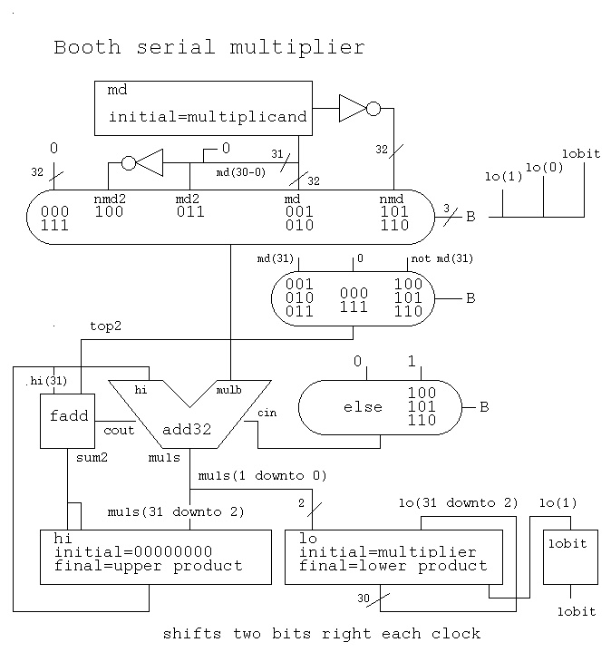
The VHDL source code for a serial multiplier, using a shortcut model where a signal acts like a register. "hi" and "lo" are registers clocked by the condition mulclk'event and mulclk='1' The VHDL is mul_ser.vhdl The output of the simulation is mul_ser.out At the start of multiply: the multiplicand is in "md", the multiplier is in "lo" and "hi" contains 00000000. This multiplier only works for positive numbers. Use a Booth multiplier for twos-complement values. At the end of multiply: the upper product is in "hi and the lower product is in "lo." A partial schematic of just the multiplier data flow isThe modified Booth serial multiplier, using a shortcut model is: The VHDL is bmul_ser.vhdl The output of the simulation is bmul_ser.out A partial schematic of the Booth multiplier data flow is
  The VHDL source code for a serial divider, using a shortcut model
  where a signal acts like a register. "hi", "lo" and quo are registers
  clocked by the condition  divclk'event and divclk='1'
  The VHDL is div_ser.vhdl
  The output of the simulation is div_ser.out

  At the start of the divide: the divisor is in "md" ,
  the upper dividend is in "hi" and the lower dividend is in "lo."

  At the end of the divide: "lo" contains the quotient and "hi" contains
  the uncorrected remainder (may need the divisor added to remainder)

  A partial schematic of just the divider data flow is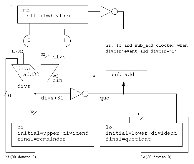
An unsigned multiplier using a carry save adder structure. The VHDL source code for a parallel multiplier, using 'generate' to make the VHDL source code small is mul32c.vhdl The test bench is mul32c_test.vhdl The output of the simulation is mul32c_test.out The VHDL source code for a parallel Booth multiplier, two's complement 32-bit multiplicand by 32-bit multiplier input producing 64-bit product is bmul32.vhdl The test bench is bmul32_test.vhdl The output of the simulation is bmul32_test.out Both VHDL models use a concurrent conditional statement to model various multiplexors. A partial schematic of the multiplier isA partial schematic of the add32csa is
An unsigned divider using non-restoring divide with uncorrected remainder. The basic cell is a Controlled Add/Subtract, CAS. A partial schematic of the divider isThe test bench is divcas4_test.vhdl The output of the simulation is divcas4_test.out
  VHDL allows a hierarchy of entities containing components.
  At each level VHDL allows multiple architectures and multiple
  configurations for each entity.

  The following two examples, ctest1 and ctest1a, show use of
  components with a configuration and use of "entity WORK."
  that does not need a configuration.

  ctest1.vhdl uses two components, fadd and add32
  with a configuration file to select the element-architecture pair from
  a library to use for each component. There could be a behavioral
  architecture, a detailed circuit architecture, a timing architecture and
  possibly others. The configuration can be used to select for each
  component the desired architecture(s).

  ctest1a.vhdl uses the same entities without
  component declarations and without a configuration. This latter case
  is not recommended for large designs or team projects.
  When designing a pipeline where all data moves to the next stage on
  a common clock, it requires two different circuits to stall the pipeline,
  depending on registers accepting data on rising or falling clock.

  Coding techniques include:
    When storage elements accept data on a rising clock
      Initialize  clk to 0  so that a transition does not occur at time zero
      The stall clock is   clk or stall

    When storage elements accept data on a falling clock
      Initialize  clk to 1  so that a transition does not occur at time zero
      The stall clock is   clk or not stall

 The schematics for the rising and falling clock cases are :


  The corresponding VHDL source code and output for the cases are:

  stall_up.vhdl and stall_up.out
  stall_down.vhdl and stall_down.out
The corresponding VHDL source code and output for the cases are:
stall_up.vhdl and stall_up.out
stall_down.vhdl and stall_down.out
  When debugging VHDL it is sometimes useful to follow every change
  to some signal. This signal tracing is easily accomplished by
  a small process.

  The technique is to have a process that monitors the signal(s)
  For each signal, say xxx, create a process in the design unit with the signal

  prtxxx: process (xxx)
            variable my_line : LINE;
          begin
            write(my_line, string'("xxx="));
            write(my_line, xxx);
            write(my_line, string'(",  at="));
            write(my_line, now);
            writeline(output, my_line);
          end process prtxxx;

  Obviously edit the above and replace  xxx  with your signal name.
  Now, every time your signal changes a line out output shows it's value
  and the time when it changed. Of particular interest is if 'U' or 'X'
  appears, meaning Uninitialized or X for "don't know" ambiguous.
  Do not use hwrite, this masks the 'U' and 'X'
  a specific example is shown below on  sum  and  cout

  An example circuit using this technique on a 32-bit ripple carry
  adder in signal_trace.vhdl
Last updated 8/20/07